
Intrinsic Safety (Ex i)
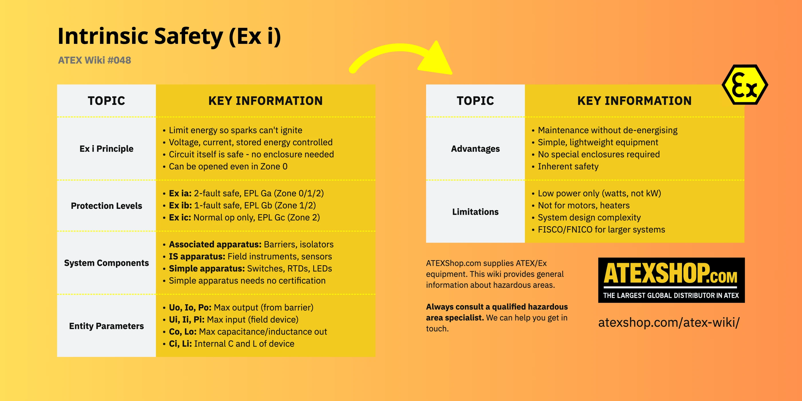
Intrinsic safety is unique among protection methods: rather than containing an explosion or preventing sparks, it limits electrical energy so that any spark that does occur cannot ignite the surrounding atmosphere. Covered by IEC 60079-11, intrinsic safety is the preferred method for instrumentation, process measurement, and control circuits in hazardous areas.
The Intrinsic Safety Principle
An intrinsically safe circuit cannot release sufficient electrical or thermal energy to cause ignition of a specific explosive atmosphere under prescribed test conditions (which include normal operation and specified fault conditions). This is achieved by limiting voltage, current, and stored energy below ignition thresholds.
The beauty of intrinsic safety is that no enclosure, seal, or barrier is needed to isolate the circuit from the hazardous atmosphere; the circuit itself is safe. This allows simple, lightweight devices that can be opened for maintenance even in Zone 0.
Protection Levels: ia, ib, ic
IEC 60079-11 defines three levels based on fault tolerance:
- Ex ia: Remains safe with two countable faults applied, plus safety factor of 1.5 on ignition curves. Achieves EPL Ga, suitable for Zone 0, 1, and 2 (Category 1)
- Ex ib: Remains safe with one countable fault, safety factor of 1.5. Achieves EPL Gb, suitable for Zone 1 and 2 (Category 2)
- Ex ic: Safe in normal operation only, no fault tolerance required. Achieves EPL Gc, Zone 2 only (Category 3)
System Components
An intrinsically safe system typically comprises several elements:
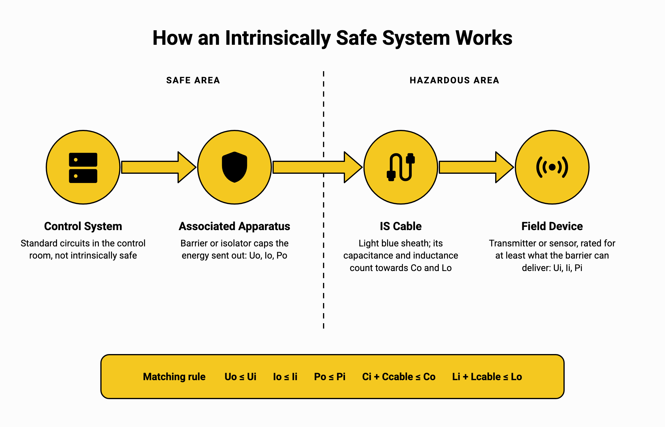
Associated apparatus: Contains both intrinsically safe circuits (connecting to hazardous area) and non-intrinsically safe circuits (connecting to safe area). Barriers, isolators, and power supplies are associated apparatus; they provide energy limiting and isolation.
Intrinsically safe apparatus: Devices intended for use entirely in hazardous areas where all circuits are intrinsically safe. Examples include field instruments, transmitters, and sensors, as well as handheld devices with their own battery, such as intrinsically safe radios.
Simple apparatus: Devices with no energy storage (e.g., switches, thermocouples, RTDs, LEDs) that cannot affect intrinsic safety. These don't require certification but must meet defined criteria.
Entity Parameters
Matching system components requires comparing "entity parameters", safety-relevant electrical characteristics:
- Uo, Io, Po: Maximum output voltage, current, power from associated apparatus
- Ui, Ii, Pi: Maximum permitted input values for intrinsically safe apparatus
- Co, Lo: Maximum capacitance and inductance permitted at output terminals
- Ci, Li: Internal capacitance and inductance of field devices
System design must ensure output limits don't exceed input maximums, and that total cable plus device capacitance/inductance stays within permitted limits.
Colour Coding
Intrinsically safe circuits are typically identified by light blue colour: in cable sheaths, terminal marking, and conductor insulation. This visual distinction helps prevent inadvertent connection to non-IS circuits during maintenance.
Advantages and Limitations
Intrinsic safety offers compelling advantages: equipment can be maintained without de-energising (even in Zone 0), simple installation without special enclosures, and inherent safety rather than reliance on mechanical protection. Limitations include restricted power levels (typically watts rather than kilowatts), making it unsuitable for motors, heaters, or high-power equipment. Modern developments like FISCO and FNICO protocols address some complexity concerns in larger installations.